Mini SDX®

Spray Characteristics

  • The Mini SDX® nozzle produces a hollow cone spray pattern with relatively uniform droplet size and particle distribution.
  • Nominal spray angle is 70°-75°.
  • Flow rates on water at 69 Bar.G. range from as low as 24.2 litres/hour to as high as 208 litres/hour, depending on nozzle size.

Features

  • The unique swirl chamber is the hear of Delavan's Mini SDX® nozzle design. The single inlet spiral configuration produces a natural, free vortex pattern. Friction is minimized, permitting 10-20% lower operating pressure than conventional slotted distributor nozzles. This lengthens both pump and nozzle life.

Construction and Materials

  • Five part construction (see part and material list below).
  • The orifice disc, a pressed fit insert, is recessed to protect against damage if dropped or hit.
  • Wrench tighten only when replacing orifice disc by pressing into nozzle body with assembly tool, otherwise no wrench tightening should be done during assembly. Wrench tightening may result in fracture of the swirl chamber.
  • The patented single inlet swirl chamber minimizes plugging and maximizes particle uniformity.
  • The Viton O-Ring seal allows assembly and disassembly without tools.
  • Only assembly tool (P/N 36386) is needed for changing the pressed fit orifice disc.

Order Example

  • When ordering specify the following:
  • 1) *Assembly part number from capacity chart*
    *or 2) Part numbers of individual items.*

Max. Design Pressure: 350 Bar.G.
Max. Design Temperature: 150°.

Mini SDX®

Features

  • The unique swirl chamber is the hear of Delavan's Mini SDX® nozzle design. The single inlet spiral configuration produces a natural, free vortex pattern. Friction is minimized, permitting 10-20% lower operating pressure than conventional slotted distributor nozzles. This lengthens both pump and nozzle life.

Construction and Materials

  • Five part construction (see part and material list below).
  • The orifice disc, a pressed fit insert, is recessed to protect against damage if dropped or hit.
  • Wrench tighten only when replacing orifice disc by pressing into nozzle body with assembly tool, otherwise no wrench tightening should be done during assembly. Wrench tightening may result in fracture of the swirl chamber.
  • The patented single inlet swirl chamber minimizes plugging and maximizes particle uniformity.
  • The Viton O-Ring seal allows assembly and disassembly without tools.
  • Only assembly tool (P/N 36386) is needed for changing the pressed fit orifice disc.

Order Example

  • When ordering specify the following:
  • 1) *Assembly part number from capacity chart*
    *or 2) Part numbers of individual items.*

Max. Design Pressure: 350 Bar.G.
Max. Design Temperature: 150°.

Assembly Procedure:

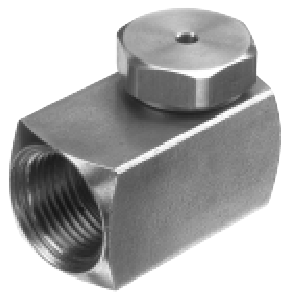
1. Place Nozzle Body (A) thread side upon a flat surface

2. Place the Orifice O-Ring (B) cone face down into the Nozzle Body (A)

3. Place the Orifice Disc (C) onto the Orifice O-Ring (B) protruding side down

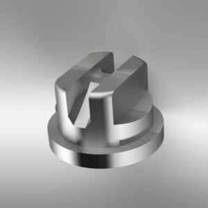
4. Secure the Swirl Chamber O-Ring (E) onto the Swirl Chamber (D)

5. Place the Swirl Chamber Assembly (D+E) swirl side down onto the Orifice Disc (C) into Nozzle Body (A)

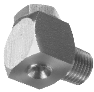
6. Secure the Adaptor O-Ring (F) into the recess on Adaptor (G)

7. Screw down the Adaptor (G) into the Nozzle Body (A) securing all components in place and hand tighten only

8. Finally ensure the complete assembly does not rattle

* Specify orifice size and swirl chamber suffix from capacity chart, on pages 24-25

Please Note: This chart is only a limited illustration of available sizes. Special materials are available on request for particular applications, please contact us for prices and delivery.

Latest News

Keep up to date with the latest news from partners, events, our company and the wider industry.

Request a Consultation

Have questions about our spray-nozzles or fluid handling systems? Looking for help on a unique application? Need help with a budget estimate to determine overall equipment costs? Please don’t hesitate to reach out — we’d love to help.