Assembly Procedure:
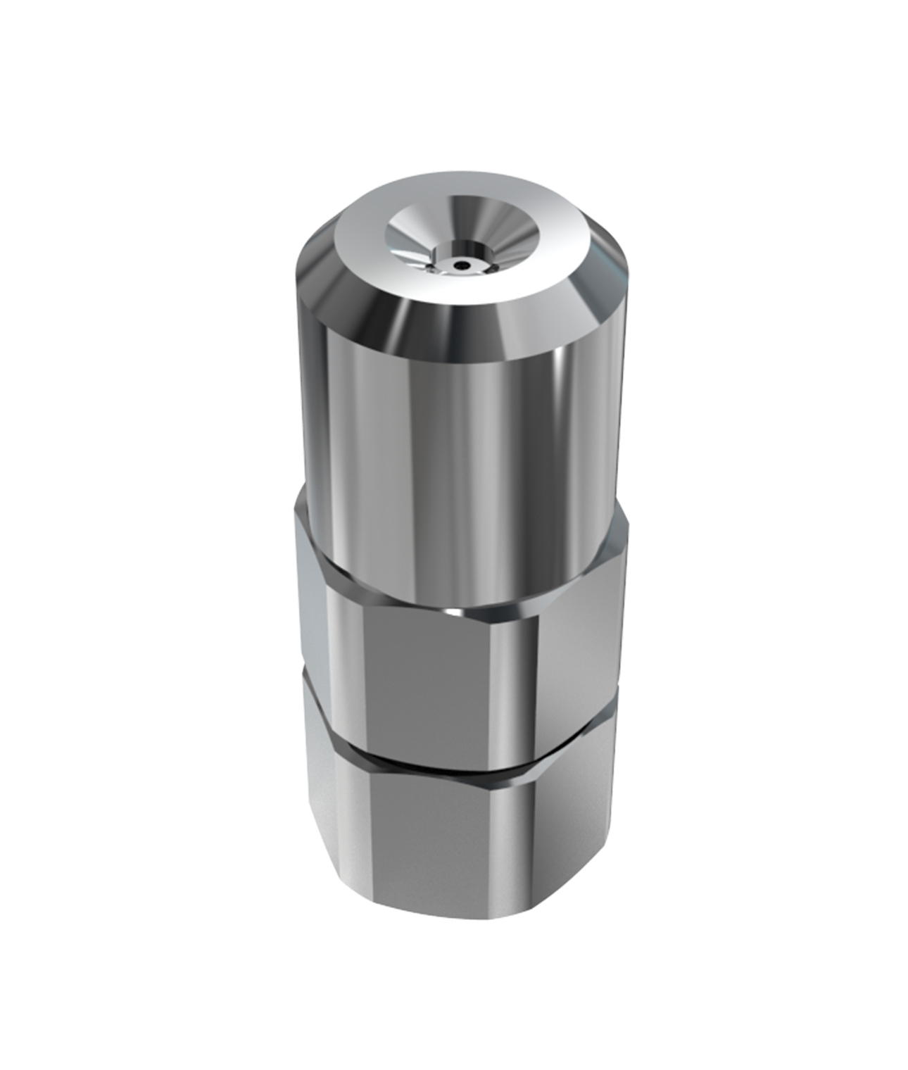
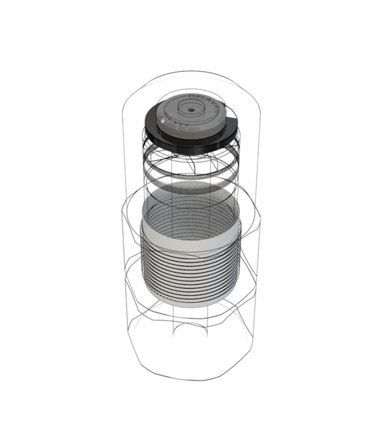
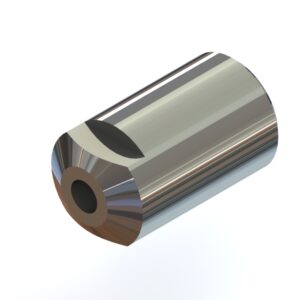
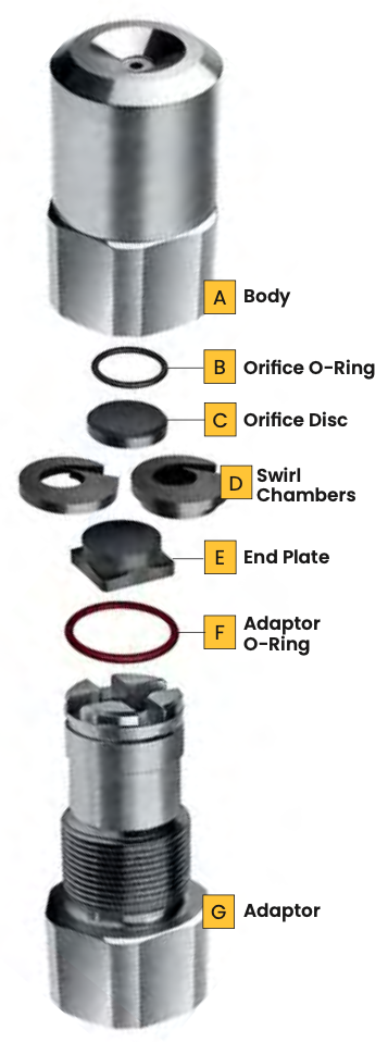
- Place Nozzle Body (A) thread side up on a flat surface
- Make sure the Orifice O-Ring (B) is pressed snugly to the Nozzle Body (A)
- Place Orifice O-Ring (C) bevelled side down into the Nozzle Body (A)
- Use a finger to align the orifice into recessed area in the Nozzle Body (A)
- Place Swirl Chamber (D) on top of Orifice Disc (C) either way up the direction does not affect functionality (W0138 will go one way only)
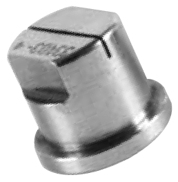
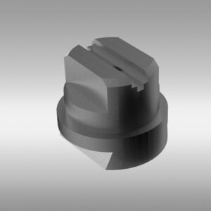
- If you require an End Plate (E) place it circular side down over Swirl Chamber (D) with square side of the end plate on top
- Make sure Adaptor O-Ring (F) is
on Adaptor (G) - Screw Adaptor (G) onto Nozzle Body (A) and hand tighten only.
- Finally ensure the complete assembly does not rattle
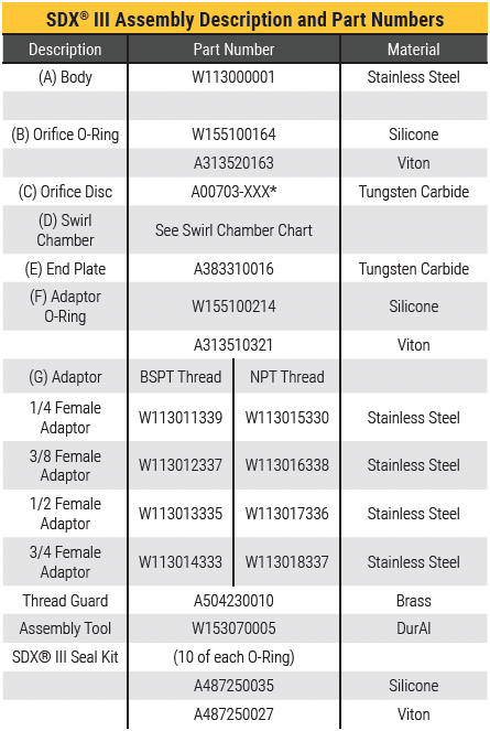
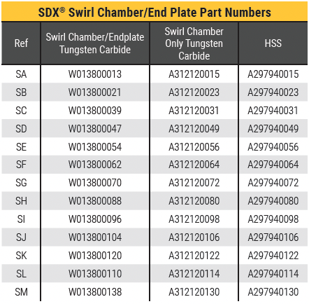
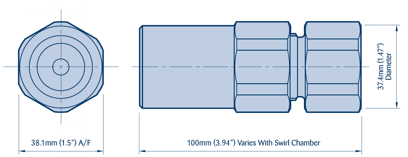
Hand tighten assembly with a maximum operating pressure 700 bar / 10150 psi is available. Maximum operating temperature to be determined by O-Ring material.
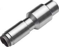
Assembly Tool
Part No. W153070005.
For the insertion of Swirl Chambers There is an additional tool number W15336 which is designed for removal of orifice discs that have become embedded with product.

Thread Guard
Part No. A504230010


