













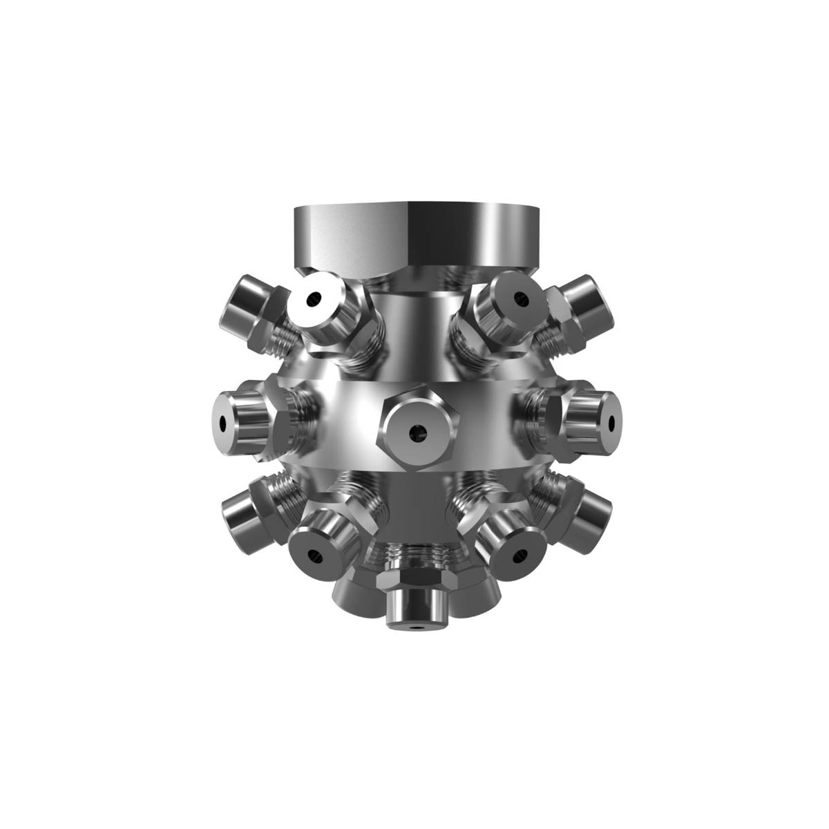
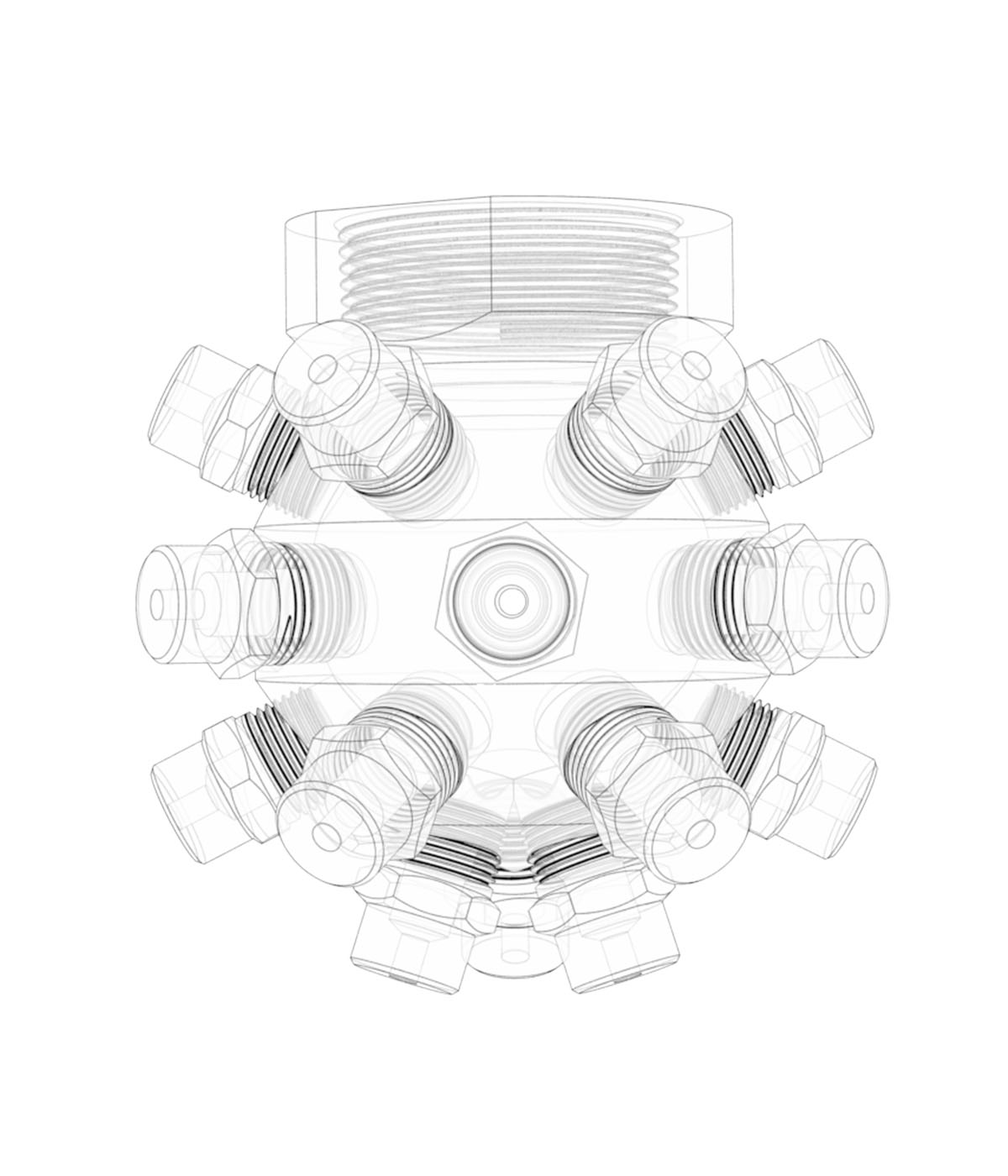
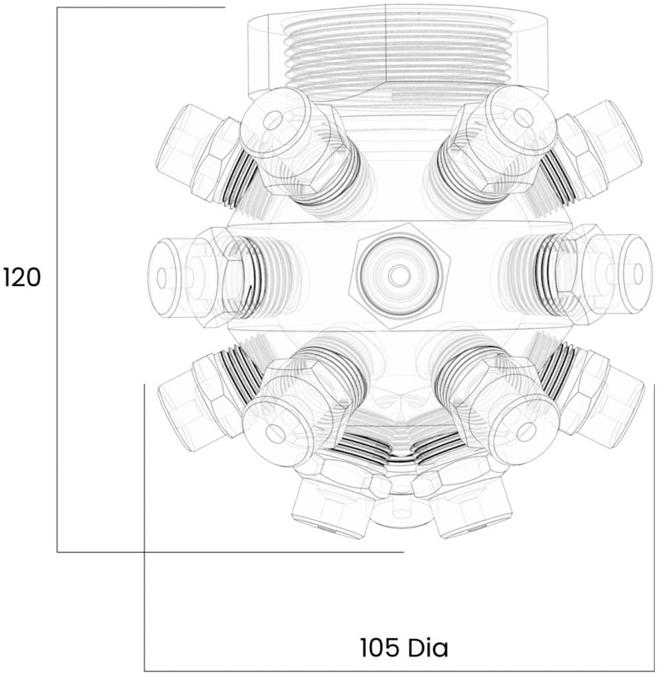
CIP21 Capacity Chart
CIP21 Chart
Assembly Number
Nozzles
Flow Rate in Liters/Min at Bar.G.
Approx. Diameter
of Coverage (mm)
Pressure Bar.G.
0,7
1,0
2,0
3,0
4,0
5,0
6,0
7,0
1,0
3,0
5,0
1.1⁄2” CIP21-150
1⁄4” BIM 6
-
31,50
45,78
55,64
60,26
67,37
71,61
74,34
1000
1900
2000
1.1⁄2” CIP21-200
1⁄4” BIM 8
-
47,87
67,83
83,98
95,55
104,8
112,9
120,1
1000
1900
2000
1.1⁄2” CIP21-250
1⁄4” BIM 12
-
71,61
95,54
111,2
124,1
138,7
147,4
159,1
1200
2400
2500
1.1⁄2” CIP21-300
3⁄8” BIM 12
58,59
69,72
99,33
122,4
138,6
154,9
163,5
171,5
1200
2400
2500
1.1⁄2” CIP21-400
3⁄8” BIM 16
75,18
92,61
128,9
152,6
167,9
187,7
199,7
210,8
1200
2400
2500
1.1⁄2” CIP21-500
3⁄8” BIM 22
107,3
131,1
174,7
205,3
229,1
256,1
277,8
298,9
1500
2990
3100
1.1⁄2” CIP21-650
3⁄8” BIM 27
126,8
155,8
211,9
258,7
286,4
320,1
337,2
366,6
1500
2990
3100
1.1⁄2” CIP21-750
3⁄8” BIM 32
152,1
186,5
258,7
303,2
335,1
374,6
405,1
428,2
1700
3300
3500
1.1⁄2” CIP21-1000
3⁄8” BIM 42
203,1
242,8
335,2
405,1
449,6
478,3
524,0
574,8
1700
3300
3500
Approx. weight of assembly=1.5Kg
Maximum Recommended Pressure: 35 Bar.G. (Metal), 7 Bar.G. (Plastic).
Literature
