







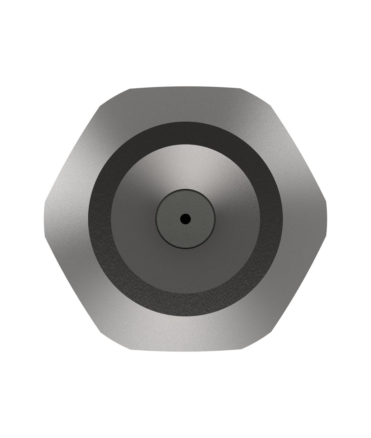
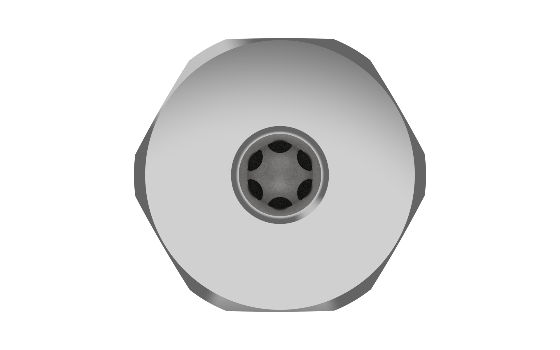
Assembly
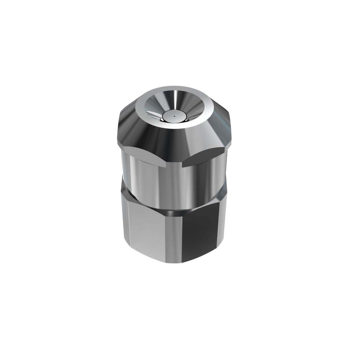
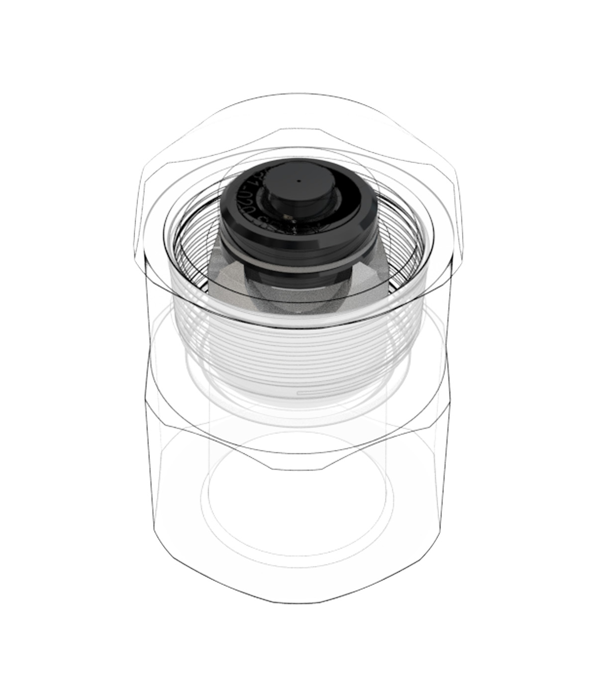
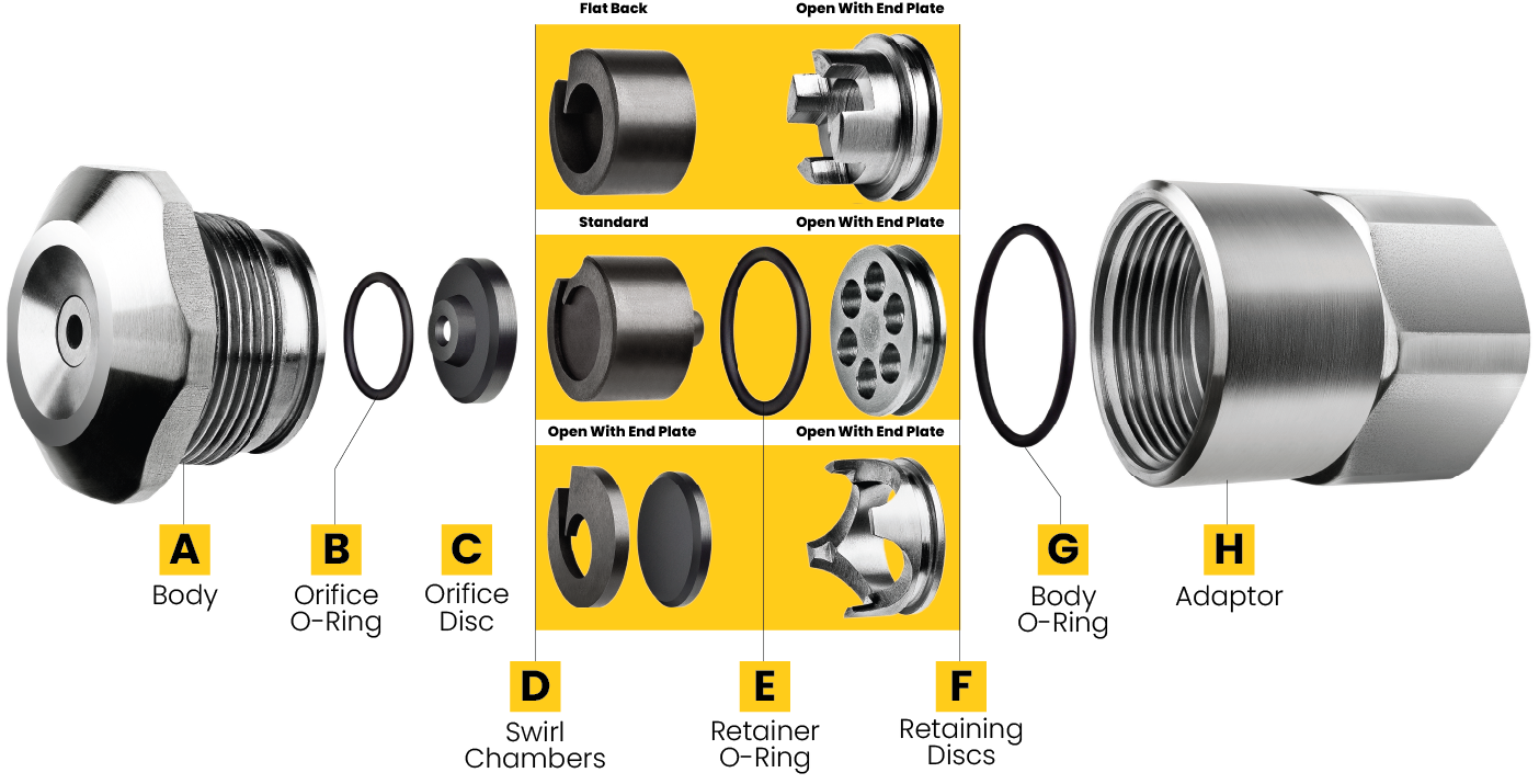
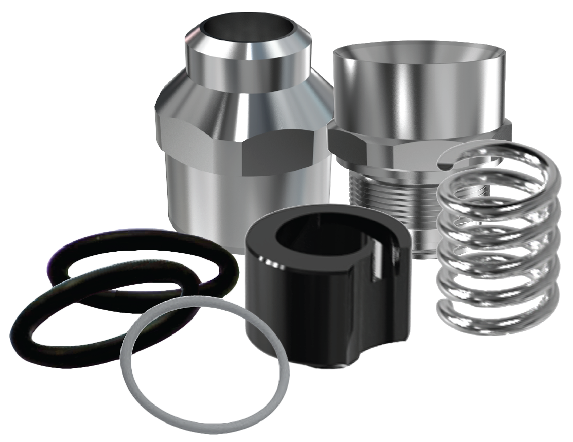
- Place Nozzle Body (A) thread side up on a flat surface
- Insert the Orifice O-Ring (B) into the Nozzle Body (A)
- Insert the Orifice Disc (C) in to the Nozzle Body (A) with the ‘orifice nose’ (the small diameter section of the orifice) inserted first so that the tapered inlet section can be seen.
- Place Swirl Chamber (D) on top of the Orifice Disc (C) with the ‘swirl profile’ located against the back face of the Orifice Disc (C)
- Ensure that the Retainer O-Ring (E) is fitted onto the Retaining Disc (F)
- Push the Retaining Disc (F) into the Nozzle Body (A) until unit is pressed flat against the back face of the Swirl Chamber (D) and Nozzle Body (A)
- Place the Body O-Ring (G) into the body o-ring groove positioned above the threads on the outside of the Nozzle Body (A)
- Pick up assembled unit and screw into Female Adaptor (H), hand tighten
SDX® V Assembly Description and Part Numbers
| SDX® V Assembly Description and Part Numbers | |||
| Description | Part Number | Material | |
| (A) Body | W194990013 | Stainless Steel | |
| (B) Orifice O-Ring | W155100164 | Silicone | |
| A313520163 | Viton | ||
| (C) Orifice Disc | W19581-XXX* | Tungsten Carbide | |
| (D) Swirl Chamber | See Swirl Chamber Chart | ||
| (E) Retainer O-Ring | W155100180 | Silicone | |
| A313520189 | Viton | ||
| (F) Standard Retainer | W195490013 | Stainless Steel | |
| Cross-Milled Retainer | W198300003 | Stainless Steel | |
| Crown Retainer | See Swirl Chamber Chart | ||
| End Plate | W053660012 | Tungsten Carbide | |
| (G) Body O-Ring | W155100222 | Silicone | |
| A313520221 | Viton | ||
| (H) Adaptor | BSPT Thread | NPT Thread | |
| 1/4 Adaptor | W195000010 | W196350018 | Stainless Steel |
| 3/8 Adaptor | W195000028 | W196350026 | Stainless Steel |
| 1/2 Adaptor | W195000036 | W196350034 | Stainless Steel |
| 3/4 Adaptor | W195000044 | W196350042 | Stainless Steel |
| Removal Tool | W196440025 | DurAl | |
| SDX® Adaptor | W19636 | Stainless Steel | |
| SDX® III Adaptor | W19637 | Stainless Steel | |
| SDX® V Seal Kit | (12 of each O-Ring) | ||
| W197690016 | Viton | ||
| W197690024 | Silicone | ||
* Specify orifice size and swirl chamber suffix from capacity chart.
Please Note: This chart is only a limited illustration of available sizes. Special materials are available on request for particular applications, please contact us for prices and delivery.
SDX® V Swirl Chamber Part Numbers
| SDX® V Swirl Chamber Part Numbers | ||||
| Ref | Standard* | Flat Back* | Open* | Crown Retainer* |
| SA | W194720014 | W198290014 | W209710018 | W211240012 |
| SB | W194720022 | W198290022 | W209710026 | W211240020 |
| SC | W194720030 | W198290030 | W209710034 | W211240038 |
| SD | W194720048 | W198290048 | W209710042 | W211240046 |
| SE | W194720055 | W198290055 | W209710059 | W211240053 |
| SF | W194720063 | W198290063 | W209710067 | W211240061 |
| SG | W194720071 | W198290071 | W209710075 | W211240079 |
| SH | W194720089 | W198290089 | W209710083 | W211240087 |
| SI | W194720097 | W198290097 | W209710091 | W211240095 |
| SJ | W194720105 | W198290105 | W209710109 | W211240103 |
*Standard Swirl Chamber uses Standard Retainer W195490013
*Flat Back Swirl Chamber uses Cross Milled Retainer W198300003
*Open Swirl Chamber uses Crown Retainer (Various Sizes)
*Crown Retainer Part Numbers to be used with Open Swirl Chamber
SDX® V Interface Adaptors
| SDX® V Interface Adaptors | |
| Part Number | Size |
| SDX® to SDX® V Interface Adaptor | |
| W196360017 | 1/4” NPT |
| W19636-2 | 3/8”NPT |
| W196360033 | 1/2” NPT |
| W196360041 | 3/4” NPT |
| SDX® III to SDX® V Interface Adaptor | |
| W196370016 | 1/4” NPT |
| W196370024 | 3/8” NPT |
| W196370032 | 1/2” NPT |
| W196370040 | 3/4” NPT |
Delavan® can offer a range of interface adaptors for the SDX® V nozzle. These can be used when converting from previous SDX® nozzles over to the new SDX® V nozzle. The interface adaptors are there to ensure that the same overall nozzle length of nozzle assembly is achieved.
SDX® V Nozzle Range Capacity Chart
SDX® V Spray Dry Nozzle Flow Rate Charts
Orifice sizes ranging from 0.016” – 0.250” in increments of 0.001” Swirl Chambers ranging from SA (0.76mm) to SM (16mm). The Orifice and Swirl Chamber sizes below show an example of some possible combinations. with over 220 Orifice sizes and 10 Swirl Chamber variants allows us to find a combination to suit your droplet size, flow rate and spray angle requirements. All spray angles are based on water at a pressure of 1000 psi (69 bar). The Mini SDX® has a nominal spray angle of 70º- 75º due to it’s unique cone faced orifice.
| SDX® Nozzles Range Capacity Chart | |||||||||||||||
| Metering Sets (Swirl Chamber/Office) | Spray Angle | ||||||||||||||
| Swirl Chamber Type | Orifice | (1000 PSIG) | Flow Rate in Liters/HR at BAR G | Flow Rate in USGPH at PSIG | |||||||||||
| Mini SDX® | Compact SDX® | SDX® & SDX® III | SDX® V | Orifice Dia (in) | Measured with Water | 69 | 138 | 207 | 276 | 345 | 1000 | 2000 | 3000 | 4000 | 5000 |
| SW4 | — | — | — | 0.016 | 70°-75° | 21 | 30 | 37 | 42 | 47 | 6 | 8 | 10 | 11 | 12 |
| SW4 | — | — | — | 0.018 | 70°-75° | 24 | 34 | 42 | 48 | 54 | 6 | 9 | 11 | 13 | 14 |
| SW4 | — | — | — | 0.020 | 70°-75° | 26 | 36 | 45 | 51 | 57 | 7 | 10 | 12 | 14 | 15 |
| SW4 | — | — | — | 0.022 | 70°-75° | 28 | 40 | 49 | 57 | 64 | 8 | 11 | 13 | 15 | 17 |
| SW4 | — | — | — | 0.024 | 70°-75° | 33 | 46 | 56 | 65 | 73 | 9 | 12 | 15 | 17 | 19 |
| — | SAC | SA | SAV | 0.025 | 68° | 51 | 72 | 89 | 102 | 114 | 13 | 19 | 23 | 27 | 30 |
| SW1 | — | — | — | 0.027 | 70°-75° | 55 | 78 | 95 | 110 | 123 | 14 | 20 | 25 | 29 | 32 |
| — | SAC | SA | SAV | 0.028 | 71° | 57 | 80 | 98 | 114 | 127 | 15 | 21 | 26 | 30 | 33 |
| SW1 | — | — | — | 0.030 | 70°-75° | 62 | 88 | 108 | 125 | 140 | 16 | 23 | 29 | 33 | 37 |
| — | SAC | SA | SAV | 0.031 | 74° | 62 | 88 | 108 | 125 | 140 | 16 | 23 | 29 | 33 | 37 |
| SW1 | — | — | — | 0.033 | 70°-75° | 66 | 93 | 114 | 132 | 147 | 17 | 25 | 30 | 35 | 39 |
| — | SAC | SA | SAV | 0.034 | 77° | 68 | 96 | 118 | 136 | 152 | 18 | 25 | 31 | 36 | 40 |
| SW1 | — | — | — | 0.036 | 70°-75° | 71 | 101 | 123 | 142 | 159 | 19 | 27 | 33 | 38 | 42 |
| — | SAC | SA | SAV | 0.037 | 79° | 76 | 107 | 131 | 151 | 169 | 20 | 28 | 35 | 40 | 45 |
| SW2 | — | — | — | 0.038 | 70°-75° | 100 | 142 | 177 | 201 | 224 | 26 | 37 | 47 | 53 | 59 |
| — | SBC | SB | SBV | 0.040 | 76° | 95 | 134 | 164 | 189 | 212 | 25 | 35 | 43 | 50 | 56 |
| SW2 | — | — | — | 0.042 | 70°-75° | 114 | 160 | 197 | 114 | 254 | 30 | 42 | 52 | 30 | 67 |
| — | SBC | SB | SBV | 0.043 | 78° | 104 | 147 | 180 | 208 | 233 | 27 | 39 | 48 | 55 | 61 |
| SW2 | — | — | — | 0.044 | 70°-75° | 119 | 168 | 207 | 238 | 266 | 31 | 44 | 55 | 63 | 70 |
| — | SBC | SB | SBV | 0.046 | 80° | 114 | 160 | 197 | 227 | 254 | 30 | 42 | 52 | 60 | 67 |
| SW2 | — | — | — | 0.048 | 70°-75° | 132 | 187 | 228 | 265 | 296 | 35 | 49 | 60 | 70 | 78 |
| — | SBC | SB | SBV | 0.049 | 81° | 121 | 171 | 210 | 242 | 271 | 32 | 45 | 55 | 64 | 72 |
| SW2 | — | — | — | 0.050 | 70°-75° | 140 | 198 | 243 | 280 | 313 | 37 | 52 | 64 | 74 | 83 |
| — | SBC | SB | SBV | 0.052 | 82° | 129 | 182 | 223 | 257 | 288 | 34 | 48.1 | 59 | 68 | 76 |
| SW3 | — | — | — | 0.054 | 70°-75° | 191 | 270 | 331 | 382 | 389 | 50 | 71 | 87 | 101 | 103 |
| — | SCC | SC | SCV | 0.055 | 78° | 170 | 241 | 295 | 341 | 382 | 45 | 64 | 78 | 90 | 101 |
| SW3 | — | — | — | 0.056 | 70°-75° | 202 | 286 | 351 | 405 | 453 | 53 | 76 | 93 | 107 | 120 |
| — | SCC | SC | SCV | 0.058 | 79° | 182 | 257 | 314 | 363 | 405 | 48 | 68 | 83 | 96 | 107 |
| SW3 | — | — | — | 0.060 | 70°-75° | 219 | 310 | 380 | 439 | 491 | 58 | 82 | 100 | 116 | 130 |
| — | SCC | SC | SCV | 0.061 | 80° | 193 | 273 | 334 | 386 | 431 | 51 | 72 | 88 | 102 | 114 |
| SW3 | — | — | — | 0.062 | 70°-75° | 231 | 327 | 400 | 462 | 516 | 61 | 86 | 106 | 122 | 136 |
| — | SCC | SC | SCV | 0.064 | 81° | 202 | 286 | 351 | 405 | 454 | 53 | 76 | 93 | 107 | 120 |
| SDX® Nozzles Range Capacity Chart | |||||||||||||||
| Metering Sets (Swirl Chamber/Office) | Spray Angle | ||||||||||||||
| Swirl Chamber Type | Orifice | (1000 PSIG) | Flow Rate in Liters/HR at BAR G | Flow Rate in USGPH at PSIG | |||||||||||
| Mini SDX® | Compact SDX® | SDX® & SDX® III | SDX® V | Orifice Dia (in) | Measured with Water | 69 | 138 | 207 | 276 | 345 | 1000 | 2000 | 3000 | 4000 | 5000 |
| — | SCC | SC | SCV | 0.067 | 82° | 212 | 300 | 367 | 424 | 473 | 56 | 79 | 97 | 112 | 125 |
| — | SCC | SC | SCV | 0.070 | 83° | 225 | 318 | 390 | 450 | 503 | 59 | 84 | 103 | 119 | 133 |
| — | SDC | SD | SDV | 0.073 | 78° | 291 | 413 | 503 | 583 | 651 | 77 | 109 | 133 | 154 | 172 |
| — | SDC | SD | SDV | 0.076 | 79° | 310 | 439 | 538 | 621 | 693 | 82 | 116 | 142 | 164 | 183 |
| — | SDC | SD | SDV | 0.079 | 80° | 325 | 462 | 564 | 651 | 727 | 86 | 122 | 149 | 172 | 192 |
| — | SDC | SD | SDV | 0.082 | 81° | 334 | 477 | 583 | 674 | 753 | 89 | 126 | 154 | 178 | 199 |
| — | SDC | SD | SDV | 0.085 | 82° | 348 | 492 | 602 | 696 | 780 | 92 | 130 | 159 | 184 | 206 |
| — | SDC | SD | SDV | 0.088 | 83° | 364 | 515 | 628 | 727 | 814 | 96 | 136 | 166 | 192 | 215 |
| — | — | SE | SEV | 0.091 | 78° | 469 | 662 | 814 | 939 | 1048 | 124 | 175 | 215 | 248 | 277 |
| — | — | SE | SEV | 0.094 | 79° | 484 | 685 | 840 | 969 | 1082 | 128 | 181 | 222 | 256 | 286 |
| — | — | SE | SEV | 0.097 | 80° | 500 | 708 | 867 | 999 | 1117 | 132 | 187 | 229 | 264 | 295 |
| — | — | SE | SEV | 0.100 | 80° | 515 | 727 | 893 | 1029 | 1151 | 136 | 192 | 236 | 272 | 304 |
| — | — | SE | SEV | 0.103 | 81° | 530 | 749 | 920 | 1060 | 1185 | 140 | 198 | 243 | 280 | 313 |
| — | — | SF | SFV | 0.106 | 76° | 723 | 1022 | 1253 | 1446 | 1616 | 191 | 270 | 331 | 382 | 427 |
| — | — | SF | SFV | 0.109 | 76° | 749 | 1060 | 1298 | 1499 | 1677 | 198 | 280 | 343 | 396 | 443 |
| — | — | SF | SFV | 0.112 | 77° | 769 | 1086 | 1332 | 1537 | 1718 | 203 | 287 | 352 | 406 | 454 |
| — | — | SF | SFV | 0.115 | 77° | 787 | 1113 | 1363 | 1575 | 1760 | 208 | 294 | 360 | 416 | 465 |
| — | — | SF | SFV | 0.118 | 78° | 814 | 1151 | 1408 | 1628 | 1821 | 215 | 304 | 372 | 430 | 481 |
| — | — | SG | SGV | 0.121 | 73° | 1003 | 1419 | 1737 | 2006 | 2244 | 265 | 375 | 459 | 530 | 593 |
| — | — | SG | SGV | 0.124 | 73° | 1026 | 1450 | 1775 | 2051 | 2294 | 271 | 383 | 469 | 542 | 606 |
| — | — | SG | SGV | 0.127 | 74° | 1052 | 1487 | 1824 | 2104 | 2354 | 278 | 393 | 482 | 556 | 622 |
| — | — | SG | SGV | 0.130 | 75° | 1079 | 1525 | 1870 | 2157 | 2411 | 285 | 403 | 494 | 570 | 637 |
| — | — | SG | SGV | 0.133 | 75° | 1105 | 1563 | 1915 | 2210 | 2472 | 292 | 413 | 506 | 584 | 653 |
| — | — | SH | SHV | 0.136 | 70° | 1567 | 2214 | 2714 | 3134 | 3505 | 414 | 585 | 717 | 828 | 926 |
| — | — | SH | SHV | 0.14 | 71° | 1628 | 2301 | 2820 | 3255 | 3641 | 430 | 608 | 745 | 860 | 962 |
| — | — | SH | SHV | 0.145 | 72° | 1703 | 2407 | 2948 | 3406 | 3808 | 450 | 636 | 779 | 900 | 1006 |
| — | — | SH | SHV | 0.15 | 73° | 1760 | 2490 | 3047 | 3520 | 3936 | 465 | 658 | 805 | 930 | 1040 |
| — | — | SH | SHV | 0.155 | 74° | 1817 | 2570 | 3145 | 3634 | 4061 | 480 | 679 | 831 | 960 | 1073 |
| — | — | SI | SIV | 0.16 | 70° | 2044 | 2892 | 3539 | 4088 | 4568 | 540 | 764 | 935 | 1080 | 1207 |
| — | — | SI | SIV | 0.165 | 71° | 2195 | 3104 | 3804 | 4391 | 4910 | 580 | 820 | 1005 | 1160 | 1297 |
| — | — | SI | SIV | 0.17 | 72° | 2347 | 3319 | 4065 | 4693 | 5246 | 620 | 877 | 1074 | 1240 | 1386 |
| — | — | SI | SIV | 0.175 | 73° | 2460 | 3478 | 4262 | 4920 | 5500 | 650 | 919 | 1126 | 1300 | 1453 |
| — | — | SI | SIV | 0.18 | 74° | 2555 | 3615 | 4425 | 5110 | 5712 | 675 | 955 | 1169 | 1350 | 1509 |
| — | — | SI | SIV | 0.185 | 75° | 2649 | 3747 | 4587 | 5299 | 5923 | 700 | 990 | 1212 | 1400 | 1565 |
| — | — | SJ | SJV | 0.19 | 71° | 3293 | 4656 | 5704 | 6586 | 7362 | 870 | 1230 | 1507 | 1740 | 1945 |
| — | — | SJ | SJV | 0.195 | 72° | 3369 | 4765 | 5836 | 6737 | 7532 | 890 | 1259 | 1542 | 1780 | 1990 |
| — | — | SJ | SJV | 0.20 | 73° | 3463 | 4898 | 5999 | 6927 | 7744 | 915 | 1294 | 1585 | 1830 | 2046 |
| — | — | SJ | SJV | 0.205 | 74° | 3634 | 5136 | 6294 | 7267 | 8126 | 960 | 1357 | 1663 | 1920 | 2147 |
| — | — | SJ | SJV | 0.21 | 75° | 3785 | 5352 | 6556 | 7570 | 8463 | 1000 | 1414 | 1732 | 2000 | 2236 |
Accessories
Literature
